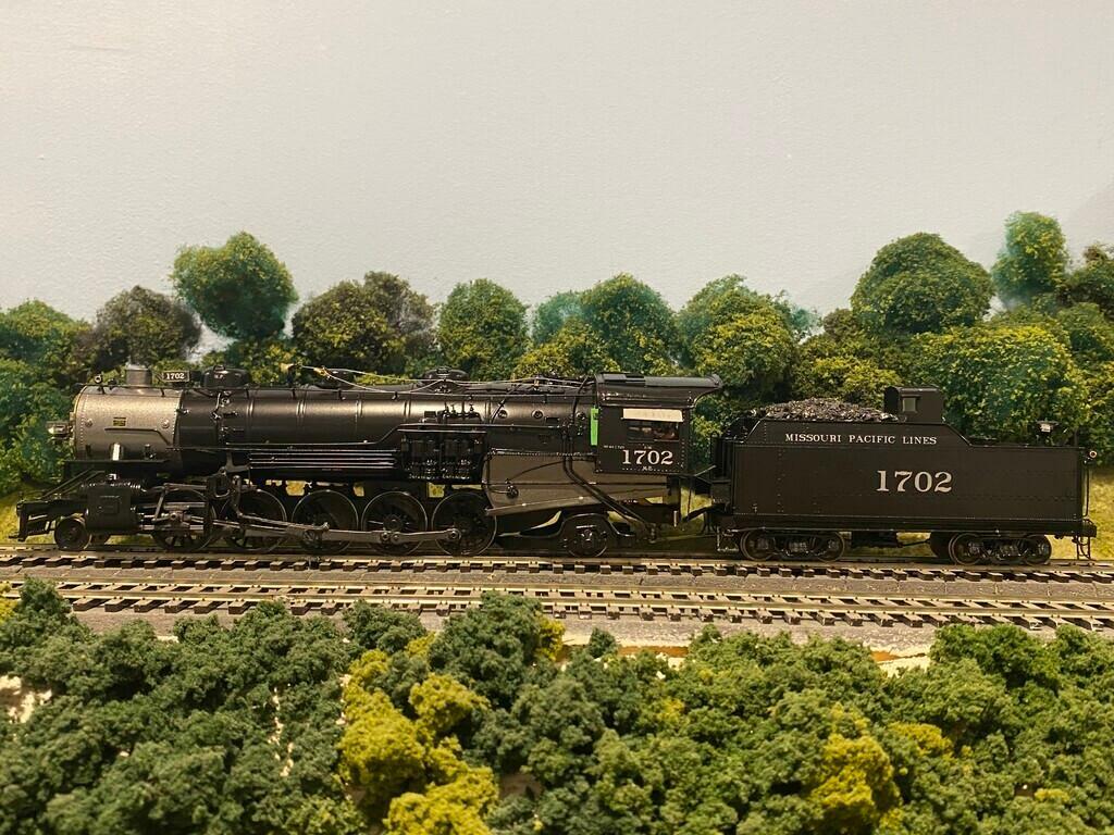
Scratchbuilding by Mike Swederska

Mike Swederska built the St. Louis Iron Mountain and Southern 2-10-2 #1702. It took him over 8 months of calendar time, with well over 450 hours in the construction phase alone. All photos and linked-to videos are copyright © Mike Swederska and photos are used by permission. The text and photos are all ones that Mike shared publicly on the Groups.io S-scale mailing list. The text has been edited to make a flowing storyline, and preserved on this page to make it easier to read. While not every step is detailed and photographed, this may still provide enough information and inspiration to start your own project.
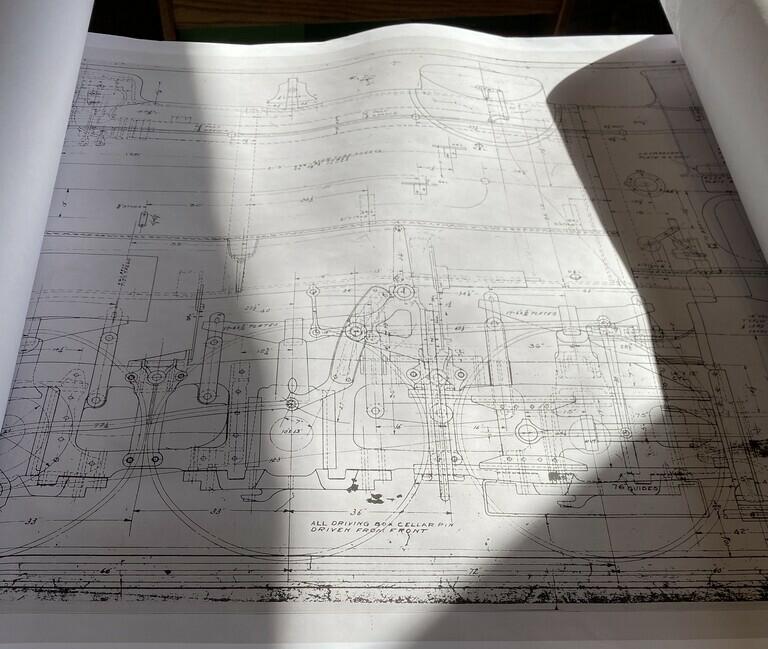
Mike started by finding prototype drawings.
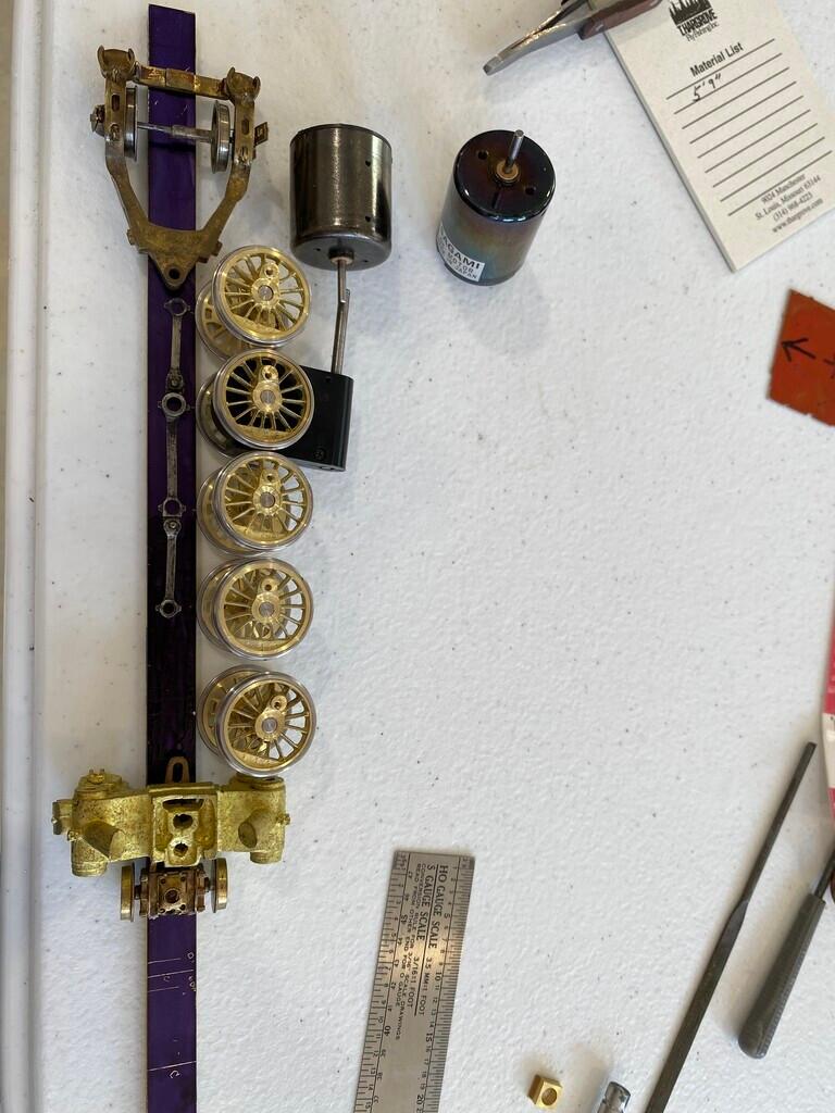
The prototype drivers were 66" apart, but between using 63" drivers and the scale flanges, Mike was concerned about their spacing. So, at this point he was debating spacing out the drivers an extra scale inch. The side rods lying on the frame material in the photo are from an S Scale Locomotive & Supply (SSL&S) 2-8-2 kit. The trailing truck, the pilot truck, and the cylinders are also from that kit and match the engine that Mike is building perfectly. The lesson here is, find as many parts that match as possible rather than building everything from scratch. The other decision Mike had to ponder was where to place the gearbox, as shown in the photo or on driver #3.
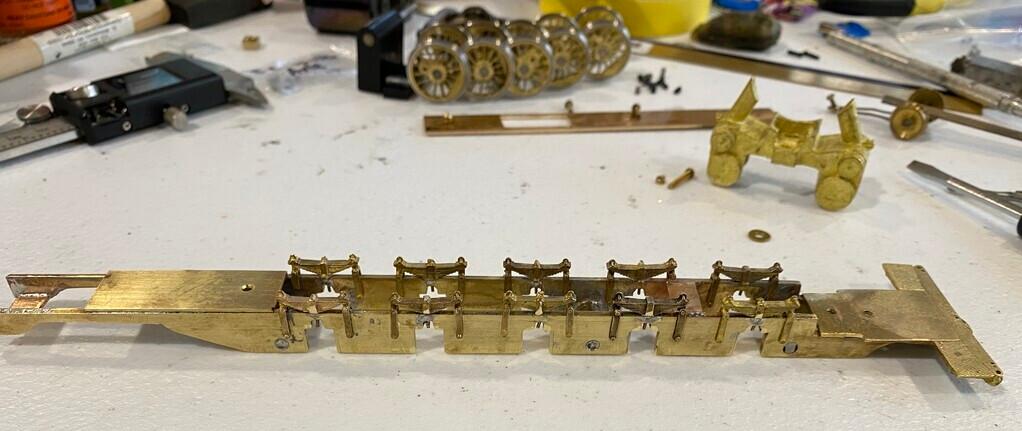
Mike built the frame, shown here upsidedown.
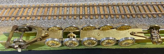
And shown right side up.

A close-up view of the top of the frame. Mike turned the frame spacers such that there is 1/16" of lateral movement allowed for the wheels, so that they can navigate curves.
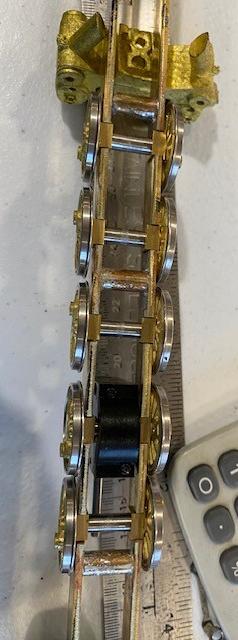
This photo shows the milling of the bearing slots.
Mike completed the frame work and all the wheels rolling square and level. The front and rear trucks were installed with some clearance from the frame. Testing it showed that everything rolled smoothly.
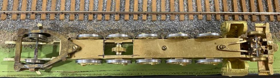
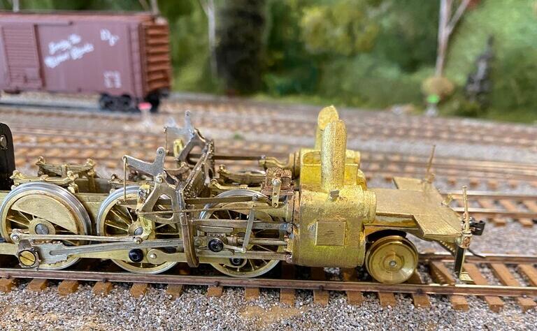
The cylinders are bolted on, and the front pilot is soldered to the top of the frame. The trailing truck axle to rear driver axle measurement is per the plans, and so is the front pilot truck axle to cylinder center. Front driver axle center to cylinder center is also per plan. The only deviation that Mike had to make so far was to reduce the axle slots separation. The photo shows the rear of the frame and the plate at the driver not being finished yet. Also, the rear trailing truck isn't level due to the screw sleeve being too long, which he was planning on making new ones for, anyway.
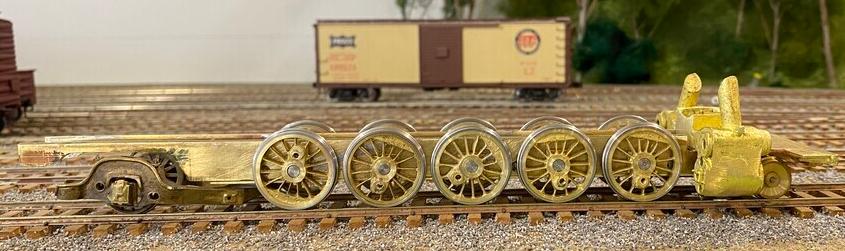
The spring pad and alignment pins are done. Springs are cut and installed. The rear frame has now been shaped. Mike noticed that it takes quite a bit of downward pressure to bottom out the springs; thinking a little more than the future finished weight of the engine. Also, the piston rod is in alignment with the axle now that the springs are in the frame.
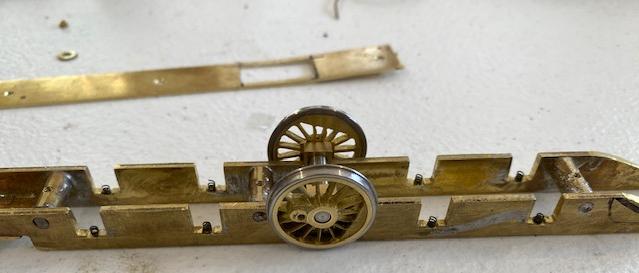
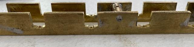
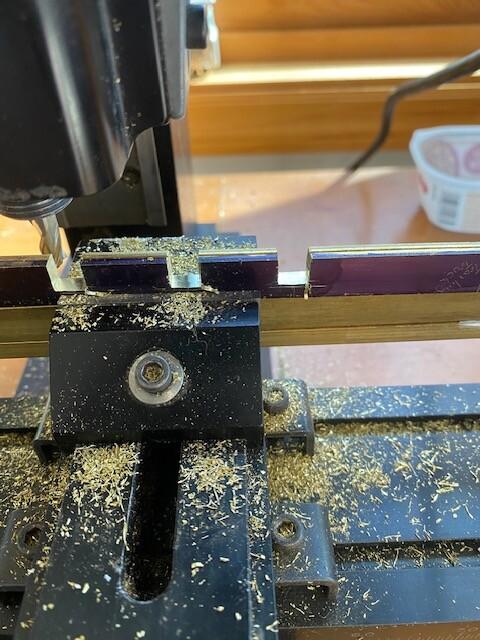
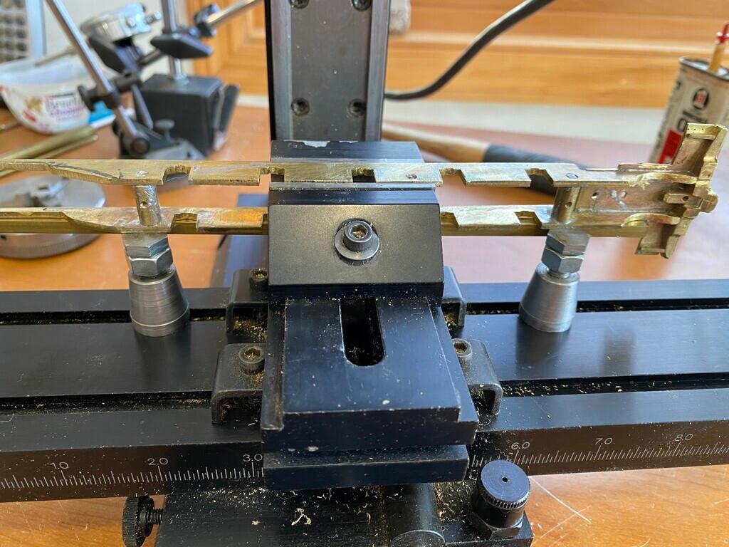
At this point in the build, Mike discovered that the frame ran beautifully on straight track and 48" radius curved track that he has on his layout, but it would bind on turnouts. Comparing this new frame to his previous builds and SSL&S kits, he found his new frame being 1/16" wider, which might be the cause of the problem. Mike went into great detail on how he fixed the issue, but to sum it up, a friend of his suggested removing the fifth wheel and see if the frame ran through the layout. It did. So, that meant that his friend, an engineer, could calculate the amount Mike had to remove from the frame to get it work with the five drivers. While doing the work, Mike discovered that the brass stock he used for the frame varied in thickness by several thousandths of an inch in its width along the frame's length. So, Mike wound up milling 0.004" off across the two length-wise side faces of the frame to reduce its overall width, and that got the frame to run with all five drivers across his layout. He did mention that if he had a layout-standard minimum of #8 turnout frogs, he probably would not have had this issue. The next photo shows his milling set-up. He removed two thousandths per each of the two passes, for each of the two sides, to achieve 0.004" per side, or 0.008" overall reduction.
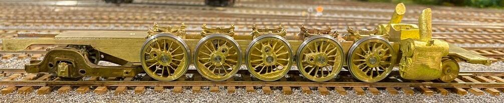
The next major decision Mike had to make was to leave the frame with unsprung drivers, which was the easy way out, or make them sprung drivers, so that it would be able to handle some of the unevennesses of his layout. The final decision was to go through the effort to make it a sprung model. He machined a slot in the bearing holes of the frame (just wider than the overall width of the spring), and then solder a metal wire (0.020") in the exact center of that slot to act as the driver coil spring holder. The top of the wire needs to be even with the bearing slot. This approach only allows a 0.020" spring action. The time-consuming part is the trial-and-error involved in finding the right spring length and tension to allow the full 0.020" movement without collapsing the spring once the full weight of the model is placed on the drivers. Mike stated that if he gets it "wrong", he had to unsolder the wire pins from the frame rails, mill the narrow slots deeper, re-solder new wire pins in place, and file them to correct length. His engineer friend came up with a way to calculate that, though. Estimate the total weight of the model (e.g. two pounds or 32 ounces). There are 10 springs, so each much be able to handle 3.2 ounces. Find 10 matched springs. Pre-load them to between 20% and 40% of their compression when the postal scale shows 3.2 ounces. Then, mill the slots for the springs to a depth of 80% of the uncompressed spring length. Then, place a 2lb weight on the frame and measure, with a dial indicator, how much the frame sags. Mike followed his friend's suggestions, and the result was a frame that didn't sag too much, but was able to navigate the layout's unevennesses without lifting the other drivers off of the track.
This is a short video showing the frame free-rolling with a pound of weights on it.
Mike built the motor mount and set the angle of the shafts. Using a 5-volt power supply he was able to verify that the drive train performed well. The motor location is measured to fit inside the firebox to the backhead. The angle is still inside that part of the boiler. Mike used the NorthWest ShortLine ball and cup for the junction of the shafts. However, he spent time to try to get the shafts to be a straight to each other as possible to minimize vibration.
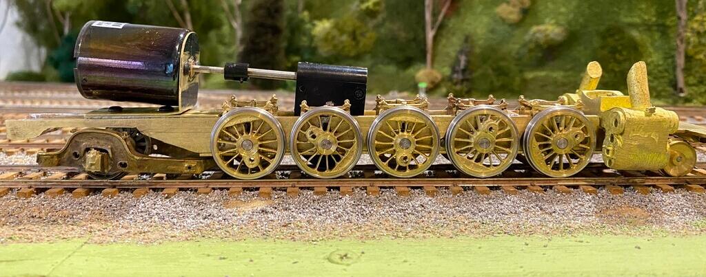
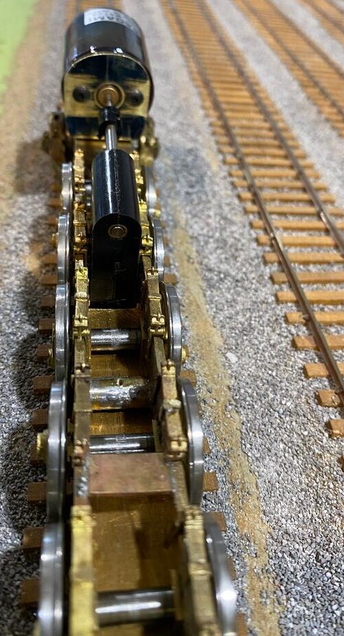
Mike shared a few photos of how he dealt with keeping the ball and cup from slipping. The tape is to prevent any foreign debris from entering.
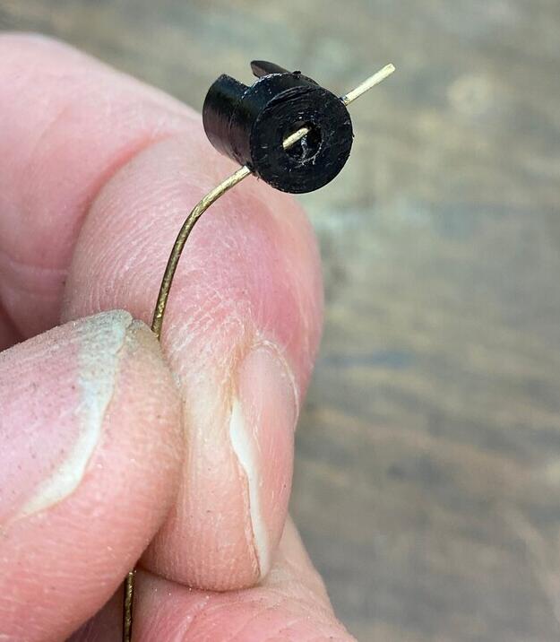
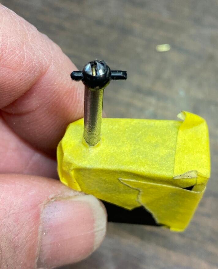
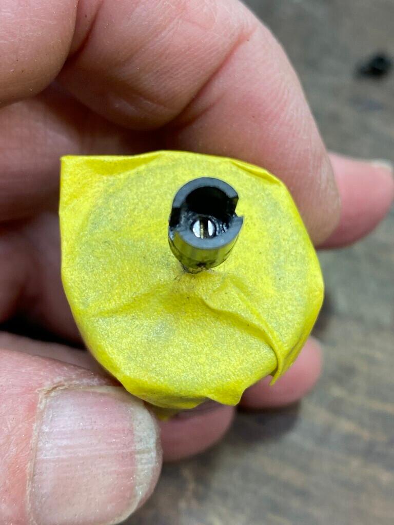
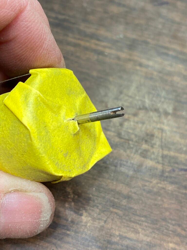
Moving to the tender frame, Mike milled the frame to take a Kadee #802 coupler. He also turned a draw bar pin for the other end of the engine.
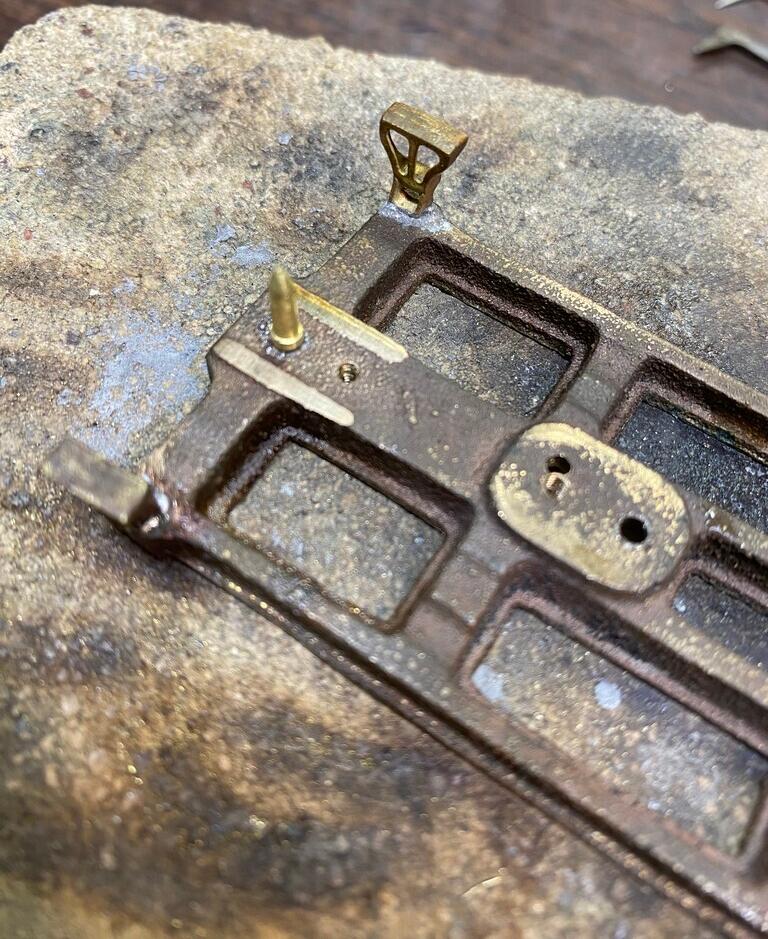
He made steel sleeves for the truck #2-56 screws.
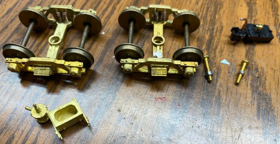
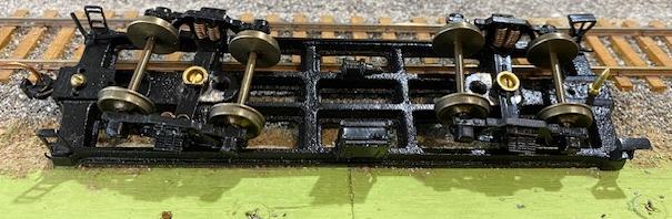
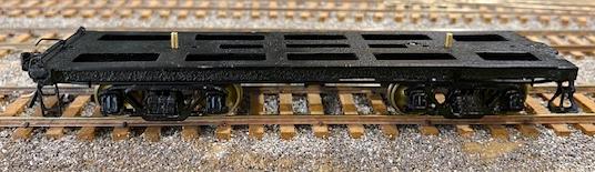
A couple of photos of the tender frame. Mike did not indicate the source of the tender frame, so the presumption is that it was part of an SSL&S kit.
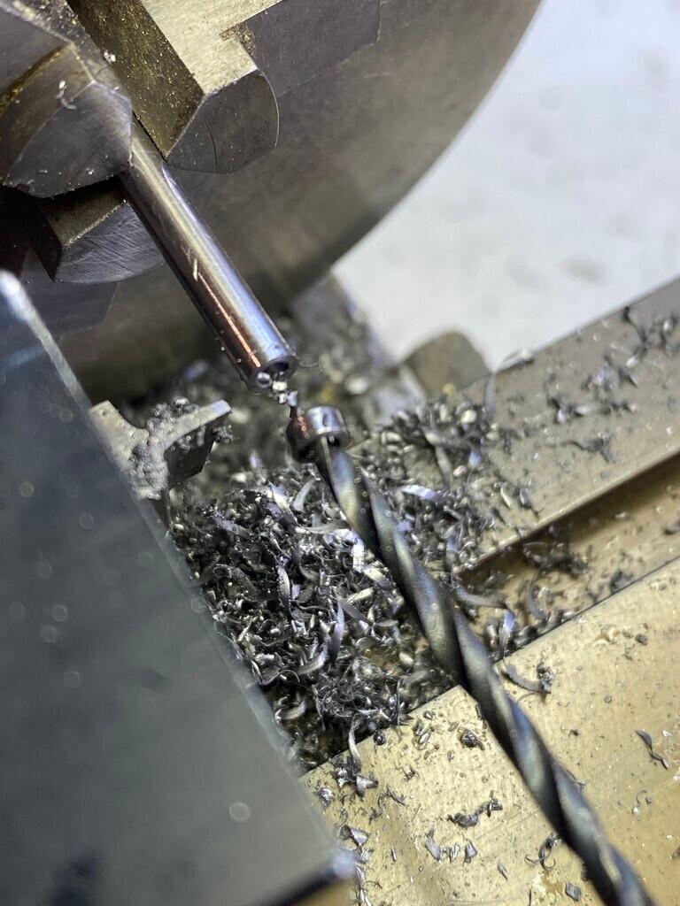
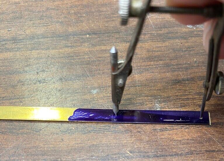
Mike made the button screw sleeves for the siderods by milling out the center of a 0.125" steel rod.
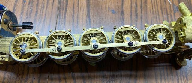
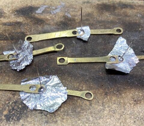
The side rods were made from 0.031" x 0.250" sheet material.
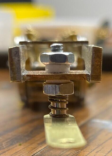
The drawbar construction. Mike shoots for 36 scale inches between the frame and the buffer. He used a #4-40 screw, the nylon bushing is from tubing he found at Lowe's, and the spring is from an ink pen. He installs the phosphorus bronze wire on top of the drawbar after he gets everything running and he knows he has the correct distance between the tender and the locomotive cab. Mike solders Tichy Train Group's phosphorus bronze 0.0015" to the top of the drawbar to conduct electricity.
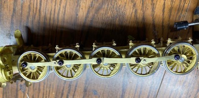
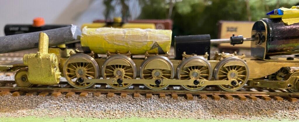
This video shows Mike running the powered frame with the tender frame on his layout, to verify that everything runs well and everything can be negotiated. The siderods are not the final ones.
It took Mike about 6 hours to make the side rods.
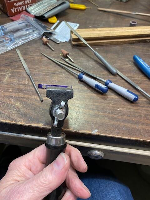
The front coupler is a Kadee #26.
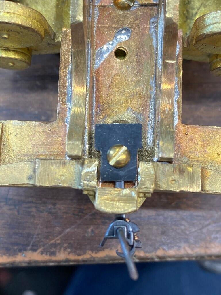
Mike completed all of the details of the pilot deck, as well as the oiler on the side of the valve gear. The oiler linkage moves back-and-forth with the reverse link.
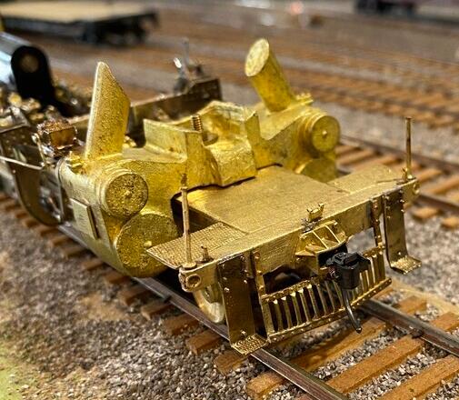
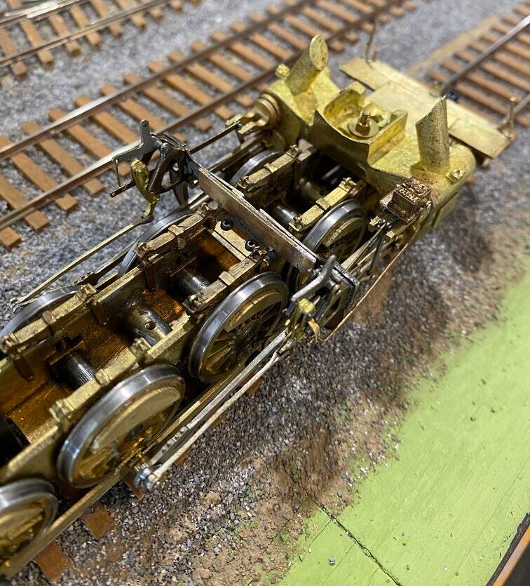
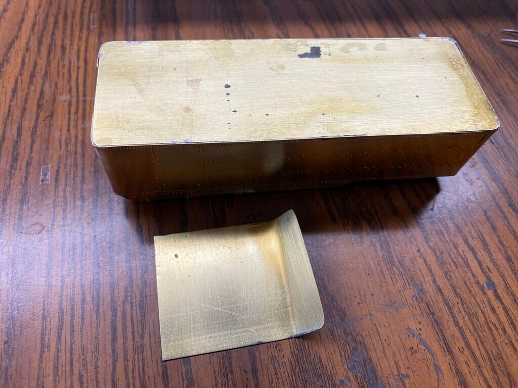
The next step was to build the main body of the tender. The top of this tender at the coal bunker curves inward on each side. Mike stated that he normally builds his tenders with a removable slope sheet, but due to the curvature of this model, he couldn't do that here. Instead, he put a solid floor in and then made a removable slope sheet that sits on a shelf and it is not quite as wide as the exterior of the tender. It fits perfectly on the edges of the curved sides and it gives him full access to the inside of this tender shell.
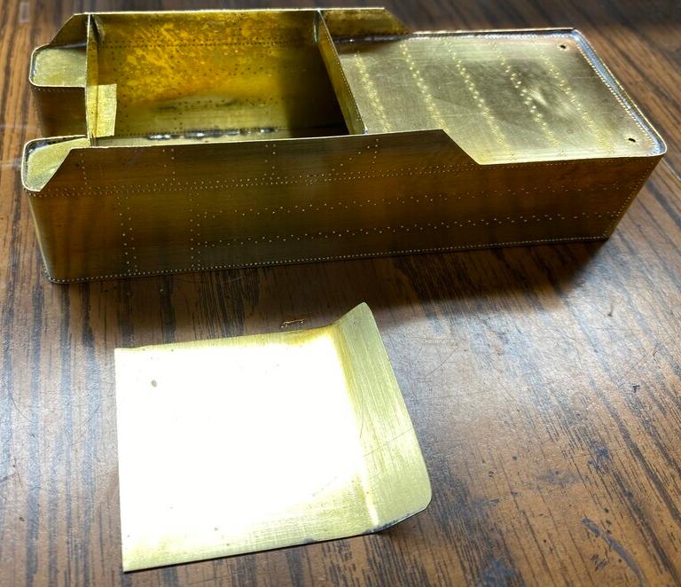
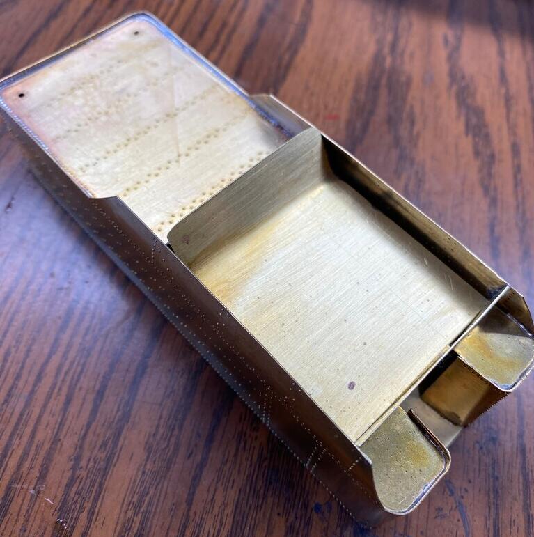
Mike discovered that he had made a mistake in routing the brake and water lines and the toolbox location the wrong way around. So, he decided to take the time to do it right, even though it set him back a bit. The other lesson learned here is that when you have that nagging feeling of something being wrong, but you don't want to take the time to do it right, it is best to just take the hit now and be happy with the final result, than to constantly be reminded of the "mistake", or having to redo it later on when the model is finished. This goes for any model.
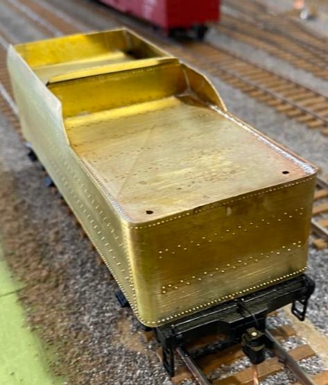
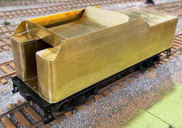
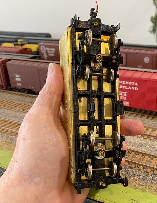
The main tender body is mostly complete. The dog house is removable.
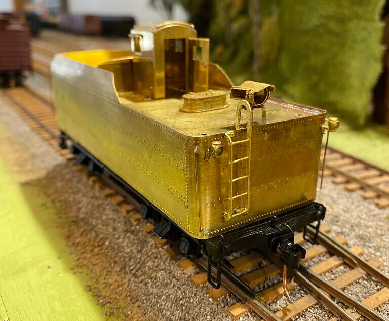
Mike has added a number of details to the tender, such as conduits, water leg valve castings, top edge flat stock, rivets, back-up light, and marker lights. The only thing remaining is the deck walkway to the locomotive.
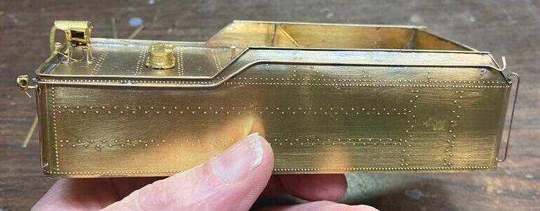
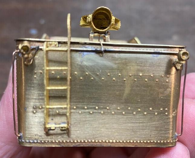
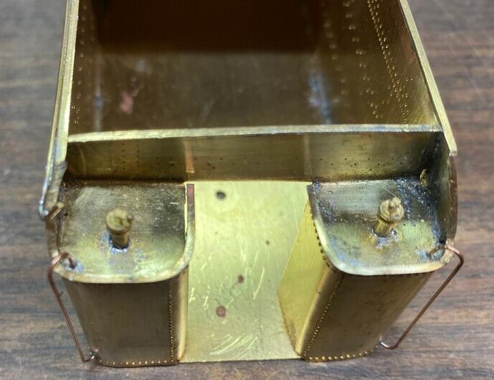
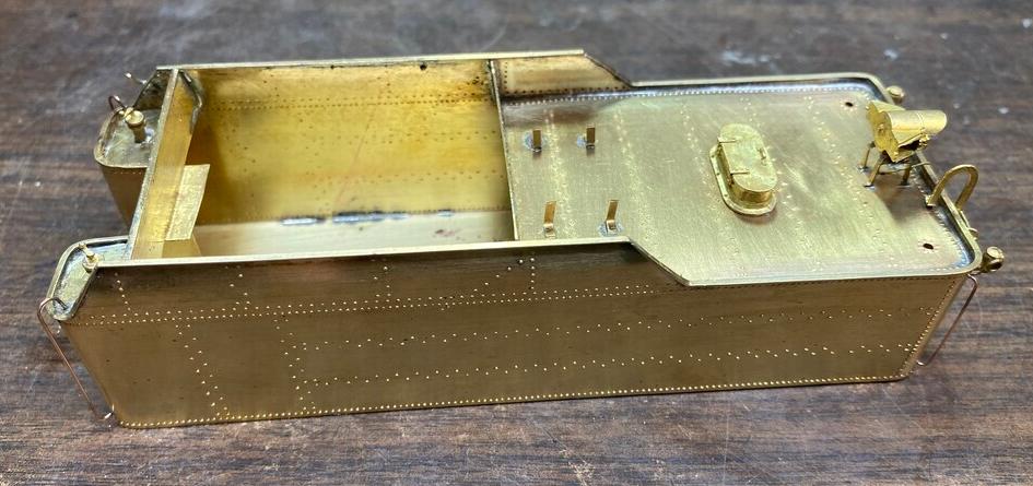
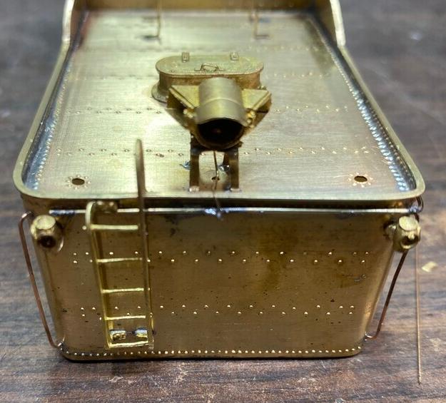
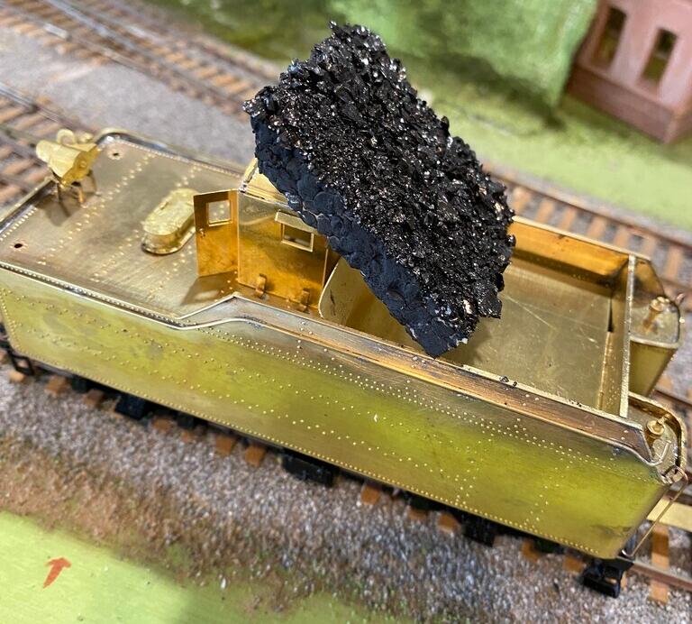
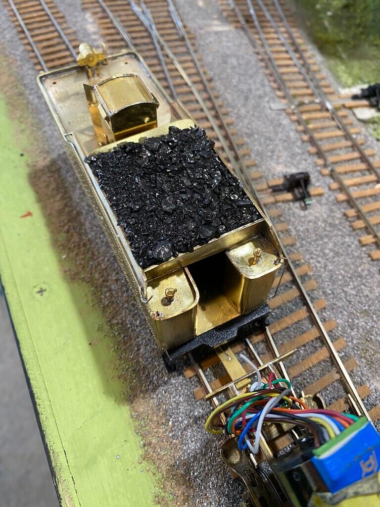
Mike glued coal bits to a foam insert, which makes it removable.
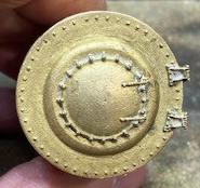
Mike found a smoke box front in his spare parts box, which saved him a ton of time. It turned out to be the perfect size for this engine.
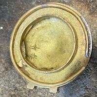
He soldered a soft brass wire on the inside lip of the part to create a "spring" to hold it on the smoke box.
This is the custom tooling and jig that Mike uses to create the rivets on the smoke box wrapper.
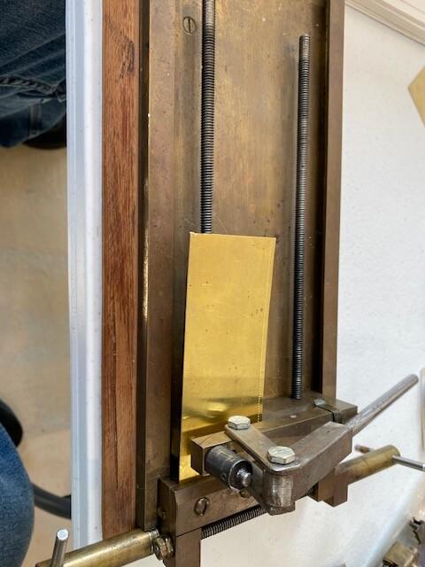
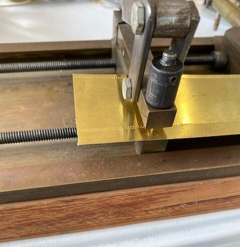
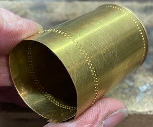
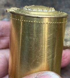
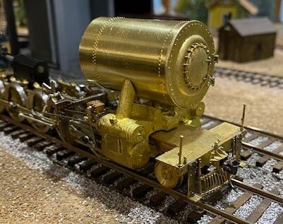
The full boiler is next. At first he rolled the sections by hand, but he wasn't happy with the results. So, he bought a slip roller and decided on using 0.016" half-hard brass sheet for rolling the sections. He said that the lesson he learned is to not be afraid to start over, even when building something out of brass.
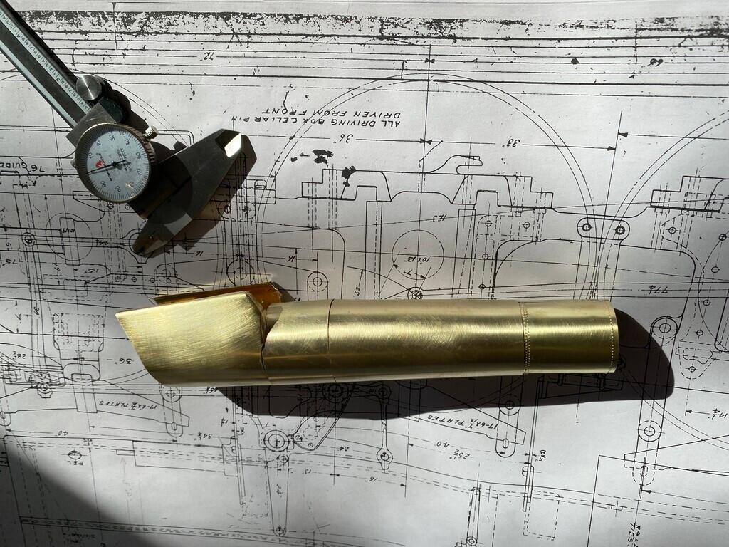
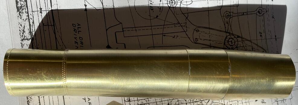
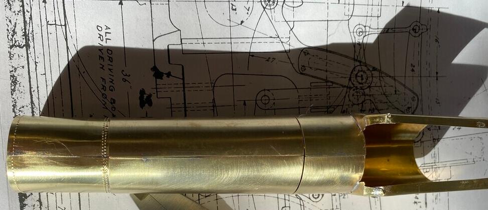
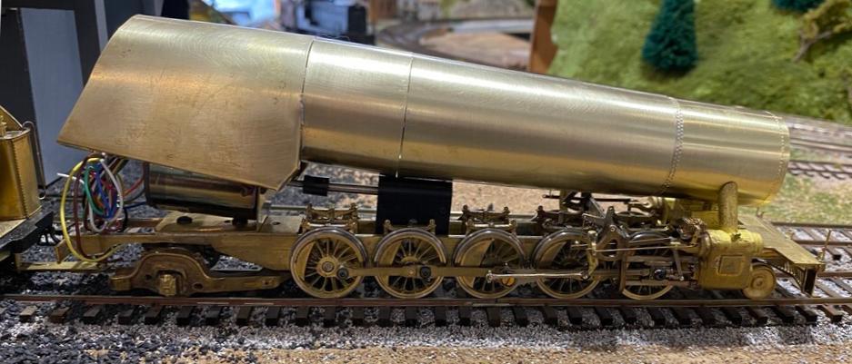
The rear dome is the same casting as the front. An SSL&S casting, but the drawing called for the rear dome to be close to a foot shorter, making it the same height as the front when installed. The boiler is much larger in diameter at that location than the front dome location. The dome casting was cut in half and the center was cut down to the correct height. All four of the grabs for both domes were formed from 0.020" wire. He used 230°F for soldering the boiler itself, and 460°F for soldering the castings to the jacketing.
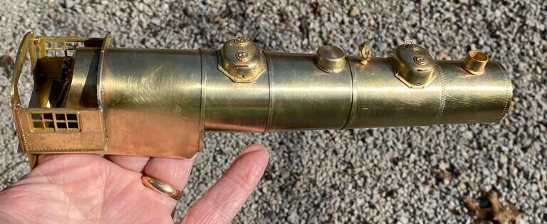
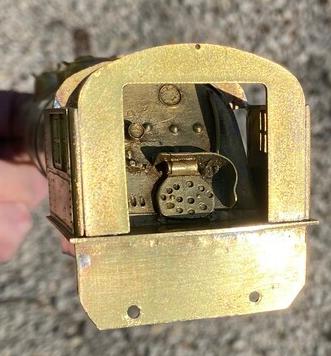
The backhead casting is of unknown origin. Precision Scale Company makes castings, primarily for narrow-gauge, but either HO- or O-scale versions can be used in S standard-gauge, as an option.
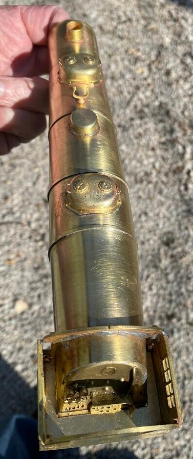
Mike put the last two boiler bands on the boiler, and cut down the bell height to match the prototype.
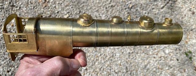
Mike used a B.T.S. headlight casting. He also used a railroad whistle casting. These saved him a lot of time. He then fabricated the throttle, and pipe that runs through the sand dome, as well as the lagging clamps on top of the boiler and the sander valves.
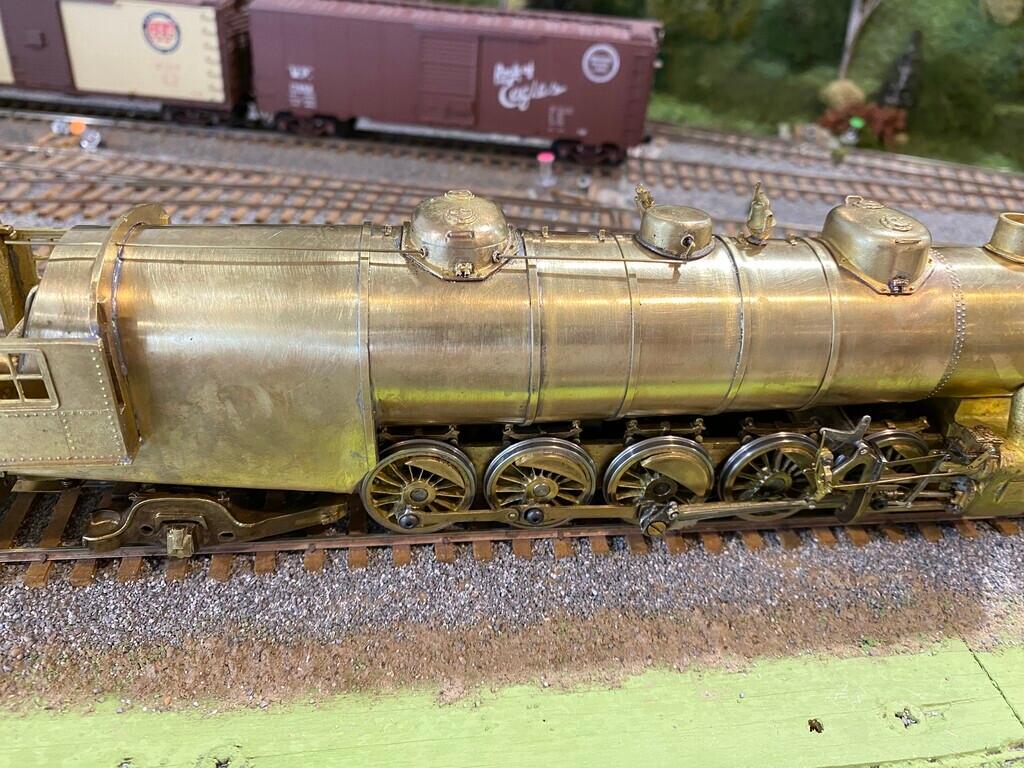
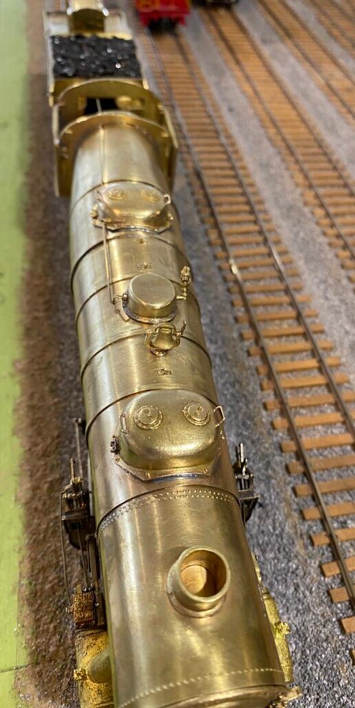
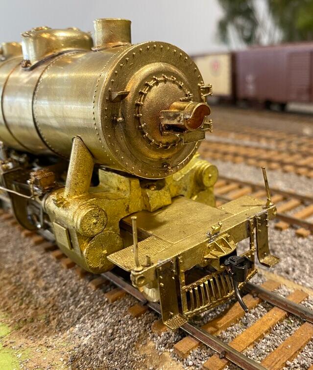
Some close-up photos of the final detailing that Mike decided upon.
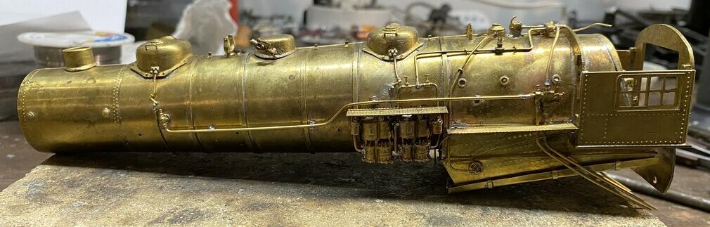
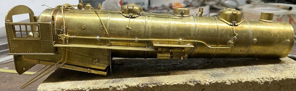
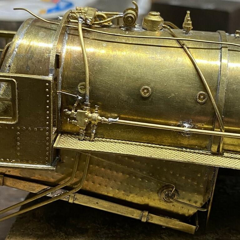
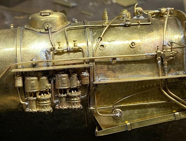
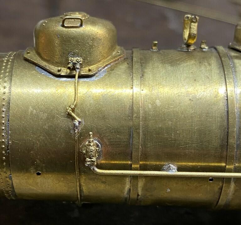
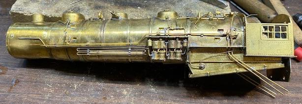
The front end, hand rails, class lights, train number boards, running board with step, and struts are done.
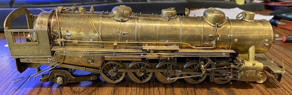
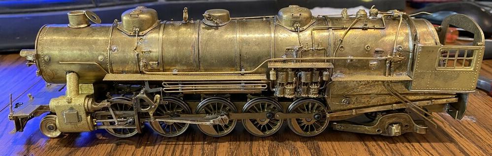
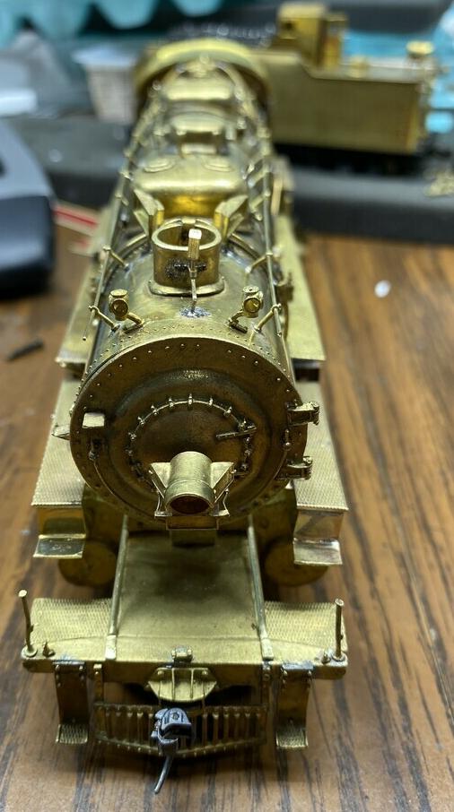
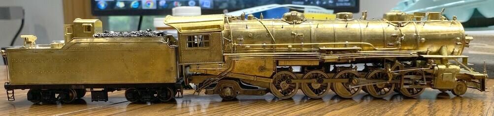
Absolute final detailing.
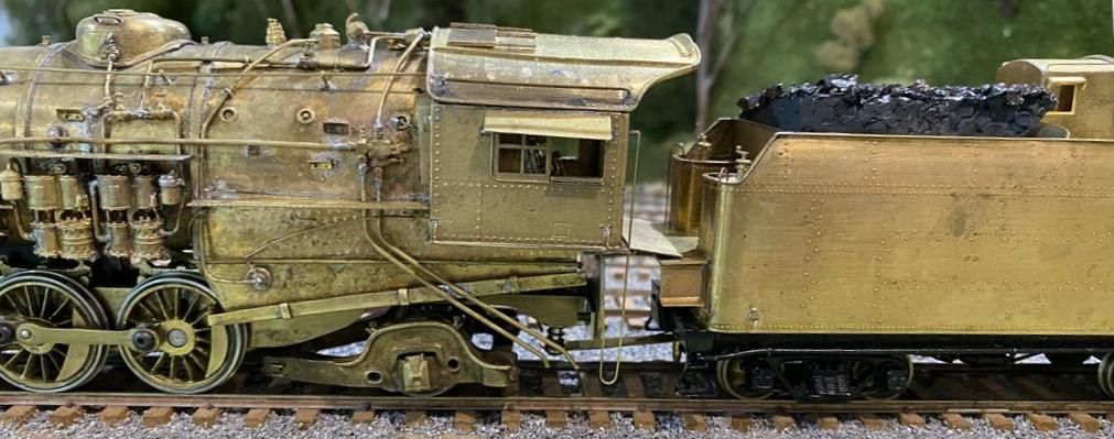
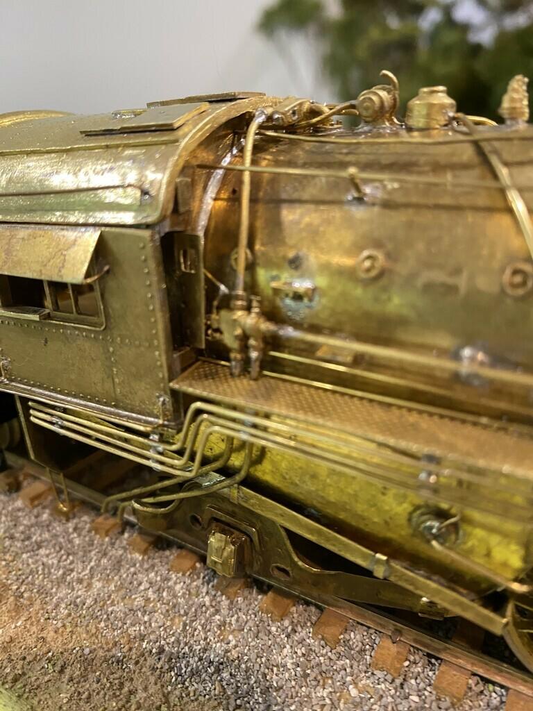
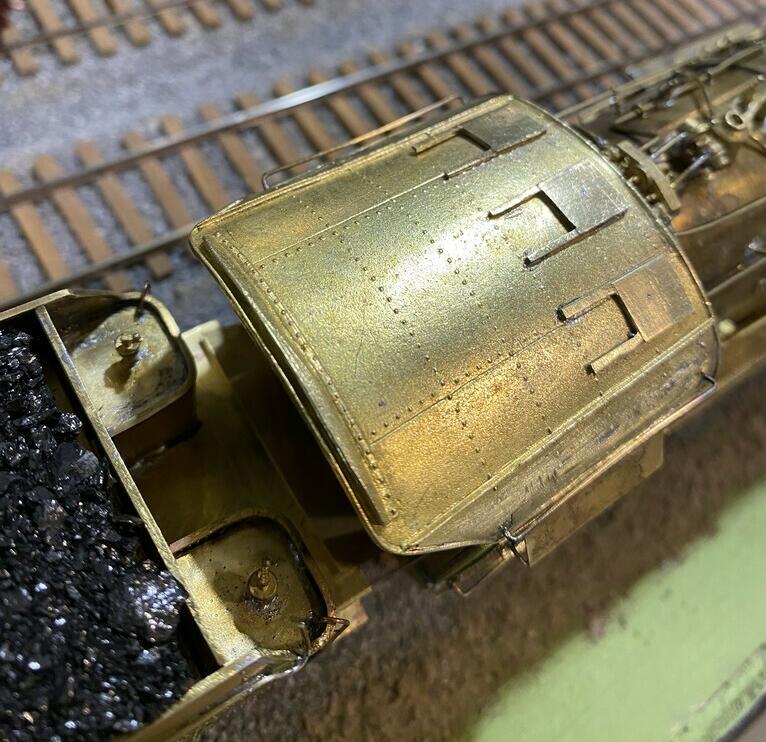
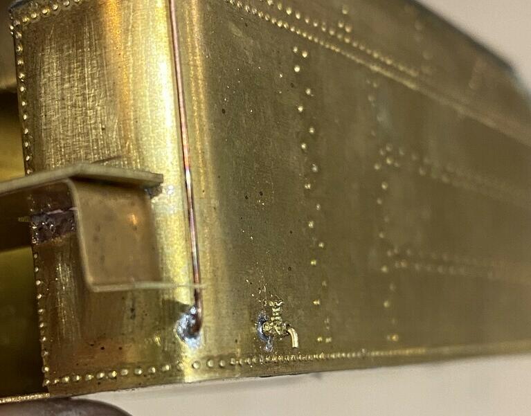
Mike stated that the tender spigot is in the prototype photo of #1702 in front of Kirkwood.
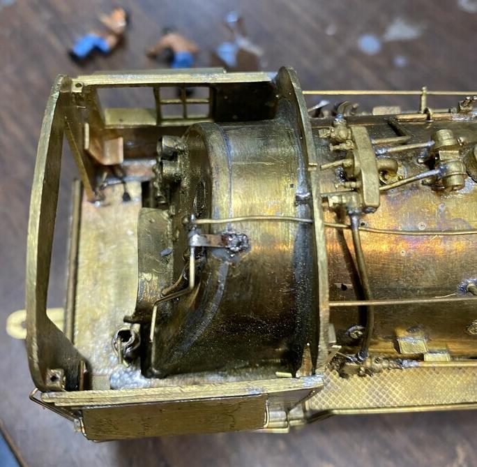
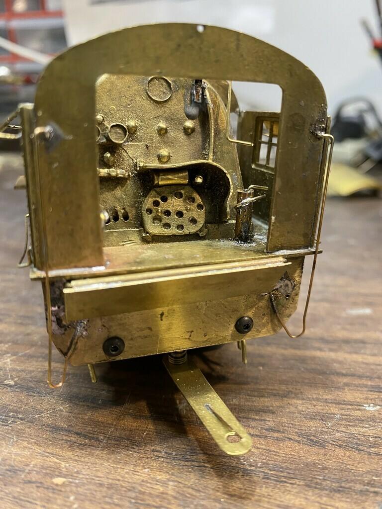
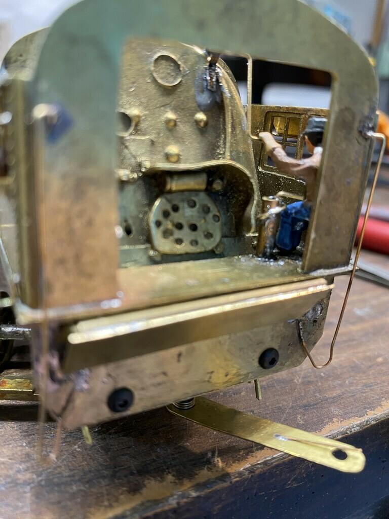
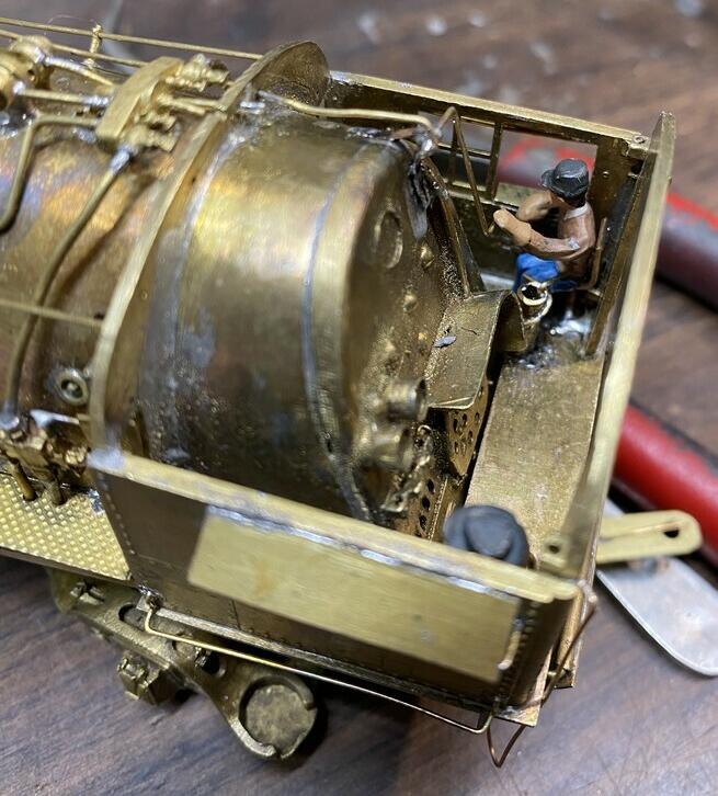
The final work was in the cab, by making and installing the crew seats, throttle, brake stand, and stoker controls.
See the built model run on Mike's layout on YouTube.
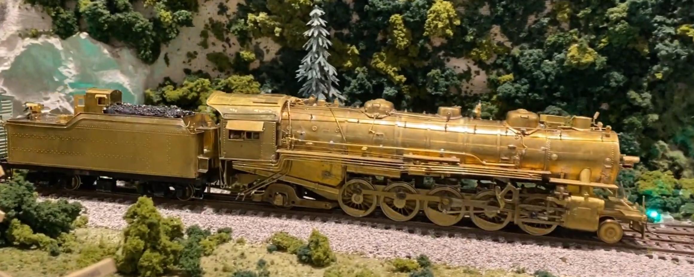
The completed model, fully painted and decals applied by Mike.